The Design
The problem with retaining the original gearbox is that it mounts directly to
the DC motor frame. Worse yet, there are no bearings in the gearbox to support
an input shaft. The motor shaft is cantilevered into the gearbox. It has a ground
surface on which the input gear slides, and has a captive key to drive the gear.
Later gearboxes had mounting feet, but mine is supported entirely by the motor.
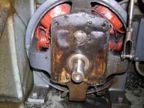
Original DC motor with gearbox removed
My first idea was to support a shaft on bearings and drive it with belts from a
base-mount motor. This had lots of potential problems:
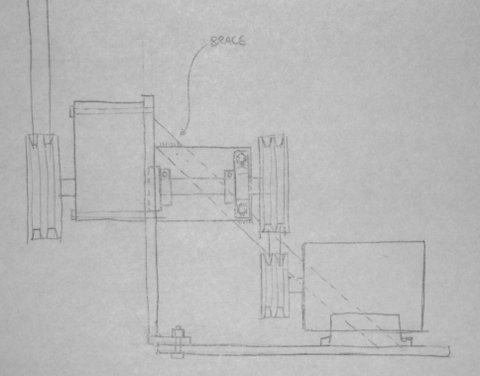
The design I finally settled on was an adapter plate and spacer assembly that
mounts the gearbox directly to both a C-face motor and the EE's motor mounting
plate. The adapter is mounted on the motor with socket-head machine
screws countersunk into the spacers. Access holes are provided so the assembly
can be removed from the motor intact.
The gearbox is mounted with hex-head bolts nutted on the far side of its plate
with pockets provided in the bottom spacer for clearance. All the parts are
permanently pinned together with pressed-in dowel pins.
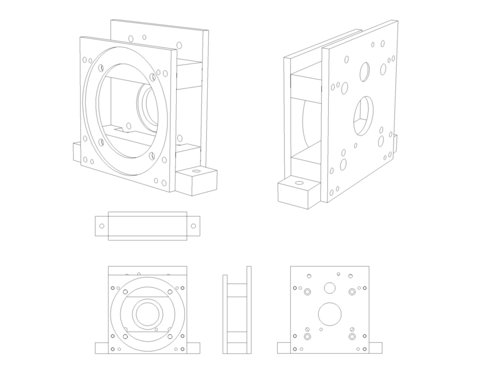
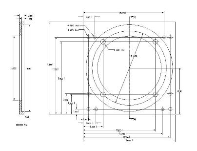
I made a full set of fabrication drawings for the parts, including drawings to
verify the motor and gearbox mounting patterns. An example:
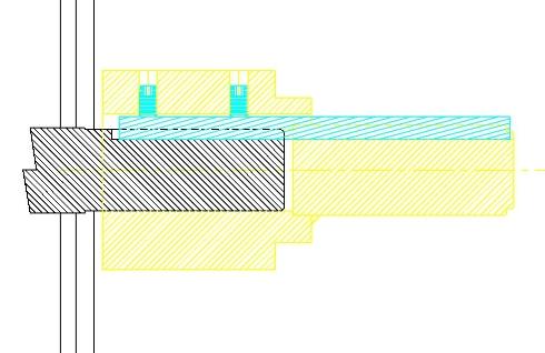
The input shaft to the gearbox is part of an adapter that mounts on the slightly
smaller motor shaft and also provides an oil seal surface and the required
captive key. Here is a cross-section:
Next Page
Back to Main Page